- 您现在的位置:买卖IC网 > Sheet目录961 > AS5030 DB (ams)BOARD DEMO AS5030
�� �
�
�AS5030�
�Datasheet� -� A� p� p� l� i� c� a� t� i� o� n� I� n� f� o� r� m� a� t� i� o� n�
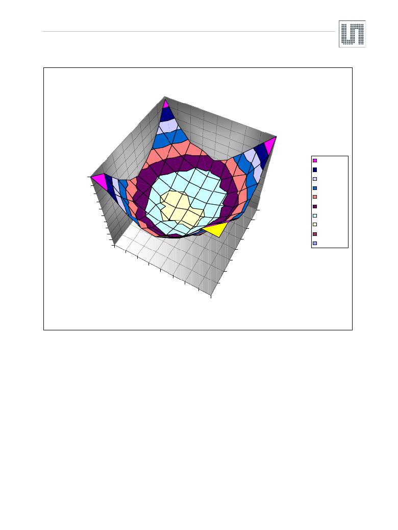
�Figure� 34.� Typical� Error� Curve� of� INL� Error� Over� Lateral� Displacement� (including� quantization� error)�
�INL� vs.� Displacement:� AS5030� for� AGC24�
�4,500-5,000�
�4,000-4,500�
�5,000�
�4,500�
�4,000�
�3,500�
�3,500-4,000�
�3,000-3,500�
�2,500-3,000�
�3,000�
�1000�
�2,000-2,500�
�INL� [°]�
�2,500�
�2,000�
�1,500�
�1,000�
�750�
�500�
�1,500-2,000�
�1,000-1,500�
�0,500-1,000�
�0,500�
�0,000�
�-1000�
�-750�
�0�
�-250�
�250�
�0,000-0,500�
�-500�
�-250�
�0�
�250�
�-500�
�-� 750�
�Y� Displacem� ent� [μm� ]�
�X� Displacem� e� nt� [μm� ]�
�500�
�750�
�-1000�
�1000�
�8.9.3�
�Magnet� Size�
�Figure� 32� to� Figure� 34� in� this� chapter� describe� a� cylindrical� magnet� with� a� diameter� of� 6mm.� Smaller� magnets� may� also� be� used,� but� since� the�
�poles� are� closer� together,� the� linear� range� will� also� be� smaller� and� consequently� the� tolerance� for� lateral� misalignment� will� also� be� smaller.�
�If� the� ±� 0.25mm� lateral� misalignment� radius� (rotation� axis� to� IC� package� center)� is� too� tight,� a� larger� magnet� can� be� used.� Larger� magnets� have�
�a� larger� linear� range� and� allow� more� misalignment.� However� at� the� same� time� the� slope� of� the� magnet� is� more� flat� which� results� in� a� lower�
�differential� amplitude.�
�This� requires� either� a� stronger� magnet� or� a� smaller� gap� between� IC� and� magnet� in� order� to� operate� in� the� amplitude-controlled� area� (AGC� >� 0�
�and� AGC� <� 63).�
�In� any� case,� if� a� magnet� other� than� the� recommended� 6mm� diameter� magnet� is� used,� two� parameters� should� be� verified:�
�??� Verify� that� the� magnetic� field� produces� a� sinusoidal� wave,� when� the� magnet� is� rotated.� Note� that� this� can� be� done� with� the� SIN-/COS-�
�outputs� of� the� AS5030,� e.g.� rotate� the� magnet� at� constant� speed� and� analyze� the� SIN-� (or� COS-)� output� with� an� FFT-analyzer.�
�It� is� recommended� to� disable� the� AGC� for� this� test.�
�??� Verify� that� the� B� z� -Curve� between� the� poles� is� as� linear� as� possible.� This� curve� may� be� available� from� the� magnet� supplier(s).� Alternatively,�
�the� SIN-� or� COS-� output� of� the� AS5030� may� also� be� used� together� with� an� X-Y-� table� to� get� a� B� z� -scan� of� the� magnet.� Furthermore,� the�
�sinewave� tests� described� above� may� be� re-run� at� defined� X-and� Y-� misplacements� of� the� magnet� to� determine� the� maximum� acceptable�
�lateral� displacement� range.�
�It� is� recommended� to� disable� the� AGC� for� both� these� tests.�
�Note:� For� preferred� magnet� suppliers,� please� refer� to� the� ams� website� (Rotary� Encoder� section).�
�www.ams.com/AS5030�
�Revision� 2.4�
�39� -� 44�
�发布紧急采购,3分钟左右您将得到回复。
相关PDF资料
AS5048-DB-1.0
BOARD DEMO AS5048
AS5215 DB
BOARD DEMO AS5215
AS5245 DB
BOARD DEMO AS5245
AS5304-DK-1.0
BOARD DEMO AS5304
AS5311 DB
BOARD EVAL FOR AS5311
ASEK712ELC-05B-T-DK
BOARD EVAL FOR ASEK712ELC-05B
ASPF240D3R
RELAY SSR 3A 240VAC SIP PHASE
ASX220A06
RELAY TELECOM DPDT 10MA 6V
相关代理商/技术参数
AS5030_07
制造商:AMSCO 制造商全称:austriamicrosystems AG 功能描述:8-Bit Programmable High Speed Magnetic Rotary Encoder
AS5030_1
制造商:AMSCO 制造商全称:austriamicrosystems AG 功能描述:8 BIT PROGRAMMABLE HIGH SPEED MAGNETIC ROTARY ENCODER
AS5030-AB
功能描述:插座和适配器 AS5030 Adapter Board RoHS:否 制造商:Silicon Labs 产品:Adapter 用于:EM35x
AS5030ATST
制造商:ams 功能描述:T&R / TSSOP 16
AS5030-ATST
功能描述:板机接口霍耳效应/磁性传感器 RoHS:否 制造商:Honeywell 类型:Bipolar Hall-Effect Digital Position Sensor 工作电源电压:3 V to 24 V 电源电流:3.5 mA 最大输出电流:20 mA 工作点最小值/最大值:5 G, 55 G 最小/最大释放点(Brp):- 55 G, - 5 G 最大工作温度:+ 150 C 安装风格:SMD/SMT 封装 / 箱体:SOT-23
AS5030ATSU
制造商:AMS 功能描述:IC MAGNETIC ROTARY ENCODER 8BIT 16-TSSO 制造商:AMS 功能描述:IC, MAGNETIC ROTARY ENCODER 8BIT 16-TSSO 制造商:AMS 功能描述:IC, MAGNETIC ROTARY ENCODER 8BIT 16-TSSOP; IC Function:Encoder IC; Brief Features:360 Contactless Angular Position Encoding, Two Digital 8-bit Absolute Output; Supply Voltage Min:4.5V; Supply Voltage Max:5.5V; No. of Pins:16 ;RoHS Compliant: Yes
AS5030-ATSU
功能描述:板机接口霍耳效应/磁性传感器 RoHS:否 制造商:Honeywell 类型:Bipolar Hall-Effect Digital Position Sensor 工作电源电压:3 V to 24 V 电源电流:3.5 mA 最大输出电流:20 mA 工作点最小值/最大值:5 G, 55 G 最小/最大释放点(Brp):- 55 G, - 5 G 最大工作温度:+ 150 C 安装风格:SMD/SMT 封装 / 箱体:SOT-23
AS5030-DB
功能描述:磁传感器开发工具 AS5030 Demo Board RoHS:否 制造商:Maxim Integrated 工具用于评估: 接口类型: 工作电压: